

 Completed
BROBOT stepper motor balancing vehicle (open source project modified version) wind control version
PRO BROBOT stepper motor balancing vehicle (open source project modified version) wind control version
License
:GPL 3.0
Description
General Introduction

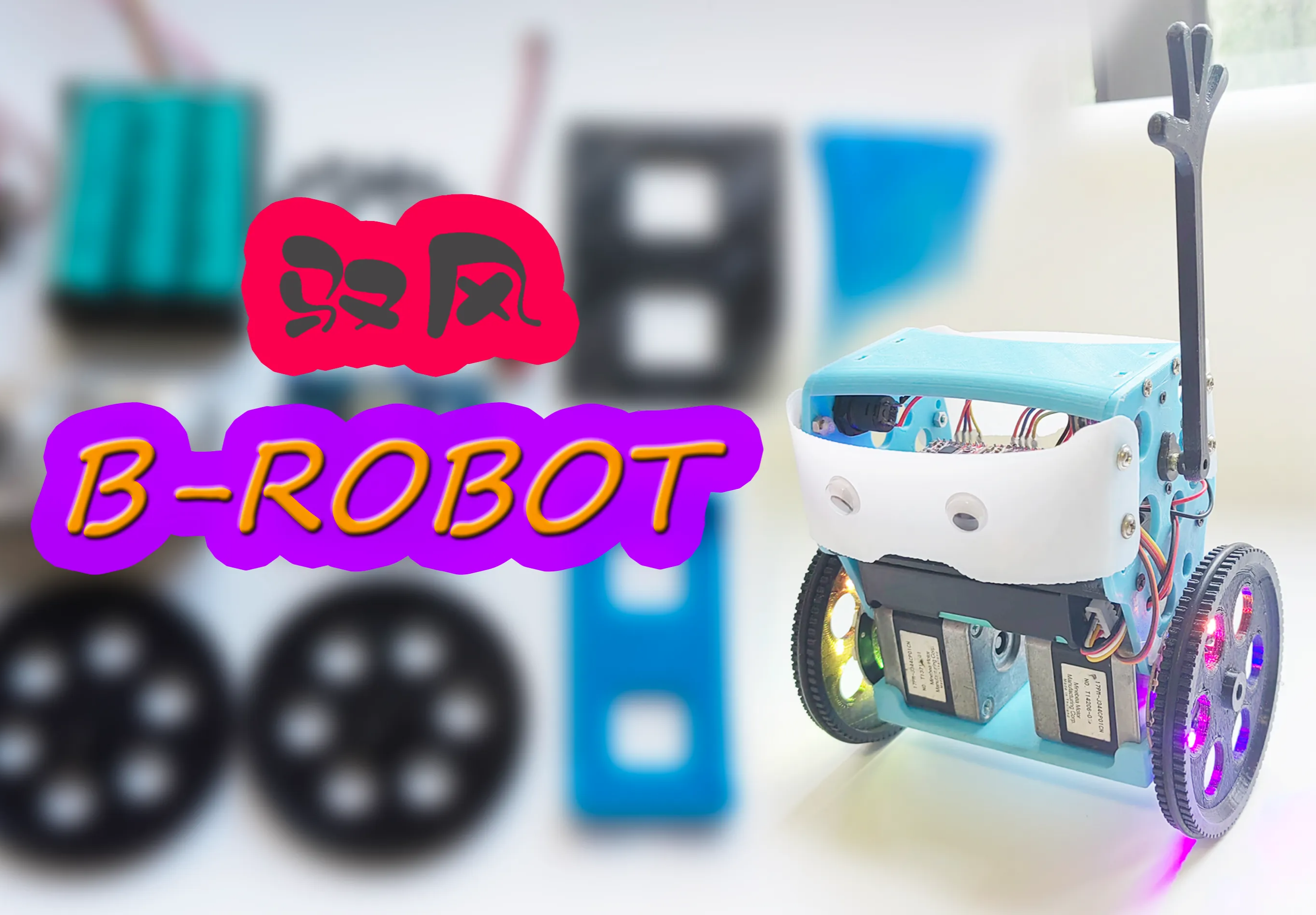
The stepper motor balance car made with reference to the open source project BROBOT has a variety of control methods. The two lantern hot wheels are extremely cool, and the control is silky and beautiful. If it falls, it can control the servo arm to automatically stand up. It is very popular. Children like it.
The main control board is ESP32, and the two 42-stepper motors are driven by two A4988 modules. The arm servo uses all-metal MG90S, and the indispensable beauty multiplier RGB light ring. The power supply uses 3 18650 batteries. In order not to take out the battery A simple battery box PCB is also designed for charging, which can be charged using a balancing charger.
I made two versions of PCB, fully modular design, with common programs, but the development boards used have different shapes. One is the most commonly used rectangular ESP32-WROOM, and the other is the smaller ESP32-Mini development board, and leads to Some IO interfaces are provided as backup.

The car body structure is modified and redrawn based on the original author's structure. The battery space is increased to accommodate three 18650 battery boxes. The self-designed wheels solve the problem of fixing the motor shaft and the list goes on.
B-ROBOT EVO2 original open source website: B-ROBOT EVO 2. Much more than a self balancing robot – jjrobots
Schematic and PCB Design
This project needs to control 2 stepper motors (5 IOs), 1 servo, 1 RGB, 1 MPU6050 (I2C), and an optional LED headlight. The overall number of IO ports required is not many , using modular design to facilitate welding and production, making it convenient for novice friends to learn and refer to.
The PCB schematics of the two versions are basically the same, except that the V2 version has some additional IO interfaces reserved for other purposes.
Fully modular design, the stepper motor driver uses A4988. For the convenience of wiring, there is no pin header + jumper cap to switch the subdivision design. The direct connection is fixed to 1/8 subdivision of A4988. If you want to change other subdivision settings Different drivers require simple modifications to the wiring.
In addition, I made a simple 3S battery box PCB, with two XH2.54 interfaces, 2P connected to the expansion board, and 4P connected to a plug. You can directly use a balancing charger to charge the battery (I use an ordinary B3 balancing charger. Pay attention to check whether the wiring sequence is the same as your own charger).
Of course, you can also use an ordinary 3-cell battery box in series. Modifying it yourself and adding a 4P plug will have the same effect, but it is not easy to solder.

Because they are all various modules, the PCB design is relatively simple. The appearance uses the same UNO shape as the original author. All modules are arranged in a compact space. The following two pictures are schematic diagrams of the two versions respectively:

The usage of "external switch or jumper cap" in the picture is that an external switch can be fixed on the right side panel of the balance car, and the switch wire is inserted here as the switch of the balance car. If this expansion board is used as it, here is Plug in the jumper cap and use the small switch on the edge of the expansion board as the power switch.
The LED headlight and current-limiting resistor (anywhere from a few hundred to 1K ohms) are only used to help determine which side is in front of the car when playing. You can choose not to solder them. Pay attention to the direction of the positive and negative poles when welding.

It can be seen that the V2 version has reserved some additional interfaces, and the motor interface can use 4P plugs or pin headers with a spacing of 2.54mm, and 4P or 6P plugs with a spacing of 2.0mm to meet the plugs of various common stepper motors. You can choose according to your own requirements. Solder the corresponding plug or pin header according to the plug type.

The simple battery box PCB has two XH2.54 interfaces (pin headers or female headers can also be used). The 2P one is the power output, and the 4P one is the balanced charger interface. Be sure to pay attention not to reverse the positive and negative poles, and be careful not to reverse the connection. or short circuit.

There is a space reserved for a 5V step-down module and a small switch on the back of the battery box, which can be used as an additional 5V output power supply after welding.
Of course, if you use an ordinary 3-cell 18650 battery box in series, you can also modify the battery box and add a 4P plug to connect to the balancing charger.
You can refer to my video on modifying the 2S battery box: https://www.bilibili.com/video/BV1VY411n7r1/?spm_id_from=333.999.0.0
Body Structure
The overall appearance is basically the same as that of the original author. I have also compiled multiple versions of open source car bodies in the data package, including various steering arm shapes, such as hammers and axes, etc. You can choose any of them.
Because the wheel shafts in the structural design of the original author and other versions are all fixed holes, when installing the motor, it is either too tight to install or too loose and slips. Even if it can be installed, it will slip after playing for a while.
So I redesigned several types of wheels with fastening functions like couplings, and selected the most suitable version after testing:

The production is relatively simple, just print it, clean the support, install the M3 screws and nuts, and install the O-type rubber seal, which is anti-slip and silent.
The light rings on both sides of the wheel are directly fixed with hot melt glue.
The rest of the changes such as battery space, servo position, switch position, etc. are not introduced one by one. The V2 version PCB reserves a pad that can be connected to a voltmeter. The battery voltage can be seen in real time to prevent over-discharge. Interested parties. Partners can try to open another fixed position for the voltmeter on the top or side panel.
Procedures and Controls
The original author of B-ROBOT uses WIFI control method and has an APP. This modified version can also support this control method. I added RGB special effects to the program.
There is a demonstration in this video of mine: https://www.bilibili.com/video/BV13Y411c7JL/?spm_id_from=333.999.0.0

But what I prefer is to use the ESP-NOW remote control I designed myself. It also supports control by a Bluetooth APP that I like, so I revised a new version of the program.
The PID control part of the main body of the program is the same as the open source program (in fact, I won't rewrite it because I am not good enough), RGB special effects are added, and the control method I like is modified.
You can watch my video demonstration: https://www.bilibili.com/video/BV17c411Z7N3/?spm_id_from=333.999.0.0

There is a switch on the remote control or APP to switch between normal (slow) mode or advanced (fast) mode. The APP supports gyro motion control.。
The left and right joysticks can be controlled with full proportional differential, and the movements are silky smooth, and the controls on the left and right can be superimposed on each other. In simple terms, it can be understood that the speed is divided into 4 levels:
Single joystick control and double joystick superimposed control are available in slow mode. Single joystick control and double joystick superimposed control are available in fast mode.
A variety of remote controls are used in the demonstration in the video. You can also use my open source Yufeng ESP_mini remote control basic version. Interested friends can learn to make one:
Yufeng ESP_Mini remote control - JLC EDA open source hardware platform (oshwhub.com)
Remote control function demonstration video: https://www.bilibili.com/video/BV1nT4y1q7AD/?spm_id_from=333.999.0.0

Installation Process Video
Installation video tutorial:https://www.bilibili.com/video/BV1WC4y1n71m/?spm_id_from=333.999.0.0

Note: Do not over-tighten the tightening screws of the imitation coupling on the wheel and cause damage. Just do not slip.
Emphasis: Be careful not to solder the positive and negative poles of the battery box backwards. Be careful to prevent short circuits during installation. Balance the 4PXH2.54 double-ended plug between the charger and the battery box and pay attention to whether the directions of the positive and negative poles are consistent. If the plug direction is wrong, you can change the plug. line sequence on.
Material Purchase
Modular PCB, the main component materials are listed below. Some pin headers, female switches, LED resistors, plugs, wires, battery boxes, etc. are not listed one by one. The 18650 battery I use is a three-cell 2000mah5C power type.
Control board related materials:

Balance car body related materials:

Note: There are many models of 42 stepper motors with different parameters, as well as two-phase four-wire and two-wire six-wire models. Some of the motor models I have tried are completely normal for use on 3D printers, and some are used for balancing. The car vibrates and stops spinning at high speeds, so I provide photos of me using a normal motor so that you can refer to it when purchasing.
In addition, the wiring of different 42 stepper motors may also be different. Unfamiliar people can search for 42 stepper motor usage tutorials to learn by themselves.

Screws and nuts:
(Be sure to buy some extra for backup)
M3*10 about 30 pieces (a small number of them can be replaced by M3*8, mainly used to fix the car body and motor, etc.)
About 20 M3 nuts.
M2*12 2 pieces (used to fix the steering gear)
M2 nuts 2 pieces.
M3*8 self-tapping screws (fixing the battery box) 4 pieces.
M2*4 self-tapping screws (fixing the rudder arm and small hand) 2 pieces.
Announcements
1. The arm servo uses all-metal MG90S. Do not use ordinary SG90, which is very easy to shake.
2. Try not to let the car stand still for a long time. It has been measured that the whole car will become hot if it stands for 20 minutes.
3. When it is stuck in a position and cannot stand up automatically, do not let the motor vibrate for a long time without turning.
4. Try to prevent children from grabbing their arms, as the steering gear is more likely to be damaged.
5. After installation and testing, it is recommended to use hot melt glue to patch the nuts to prevent them from falling off. It is better to use anti-falling nuts.
Stepper motor and A4988 driver learning
If novices want to learn about stepper motors and their drivers, it is recommended to watch Tai Chi Maker’s tutorials:
NEMA bipolar stepper motor (42 stepper motor) – Taichi Maker (taichi-maker.com)
A4988 drives NEMA stepper motor (42 stepper motor) – Taichi Maker (taichi-maker.com)
Upload Other Attachments
Contents of the attachment package:
"Collected and organized open source information of BRobot balancing car" contains several open source versions of information and APP;
"PCB data and redrawn and modified 3D files" are the data that I redid and modified, and "Simple car body version 3D files" are the print files of the simple car body;
"Programs and APPs" is my modified new version of the program, which has WIFI control method and Bluetooth/ESPNOW control method (it also supports Android mobile phone Bluetooth APP and various ESPNOW remote controls I designed).
Also: There are commonly used serial port drivers in the compressed package. Arduino IDE can be downloaded and installed from the official website: https://www.arduino.cc/en/software
When compiling and uploading a program that communicates with both Bluetooth and ESPNOW, the default settings will prompt that the occupied space exceeds the range. You only need to select a larger APP space in the partition plan of the upload settings.
For example:Minimal SPIFFS(1.9MB APP with OTA/190k SPIFFS),As shown in the figure below:

If you have any questions, you can comment or send a private message to my video at Station B. I don’t often visit Lichuang Kaiyuan Plaza. Yufeng car sharing QQ group 922620181, group 2 1011789606.
Designed by Saturn圣骑土 (from OSHWHub)
Link:https://oshwhub.com/satun/yu-feng-PICOping-heng-ju-C3U_Min
Design Drawing
Intellectual Property Statement & Reproduction Instructions
This is an open-source hardware project. All intellectual property rights belong to the creator. The project is shared on the platform for learning, communication, and research only; any commercial use is prohibited. If your intellectual property rights are infringed on EasyEDA, please notify us by submitting relevant materials in accordance with the Rules for Complaints and Appeals of IPR Infringement.
Users must independently verify the circuit design and suitability when replicating this project. All risks and consequences are borne by the user, and the platform assumes no liability.
 Empty
Empty
Comment